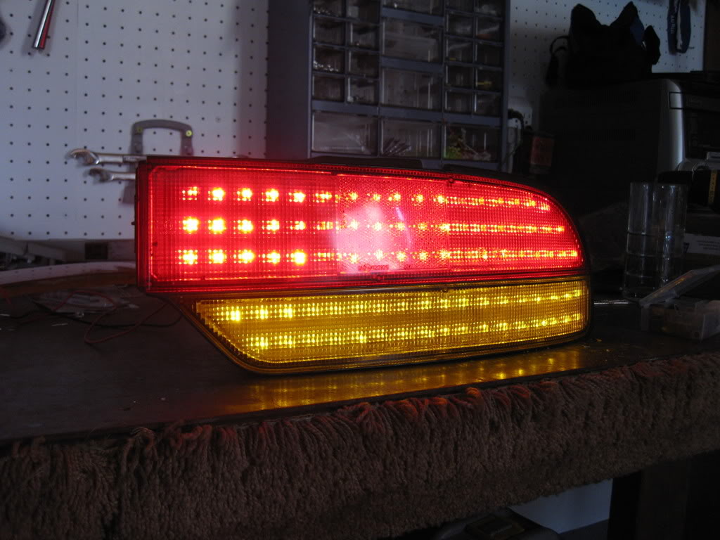
I don't know if this will be any help. But I got really interested and just started to research.
I found this on another forum. I did not do this.
Introduction
I've always been inspired by the aesthetic artistry of cars. As such I tend to obsess on the exterior modifications, always searching for a balance between something that is sleek and and catchy without being gaudy or ricey. I've seen several led replacement lenses come out for the S14, and just recently people have started to modify the s13 coupe tail lenses. However there's been little love for our S13s in the LED department apart from some questionable ebay kouki knockoffs. Anyway I was inspired by some of the other LED projects that have been posted up here in the forums, and since my s13 is 400 miles away, I decided I'd pass some time and retrofit a spare set of tails with LEDs.
So, if you liked the results of my project as seen in videos above, please feel to use this DIY to create a set for yourself.....
Disclaimer!
1. While I've managed to create working LED tail lights I've been unable to mount them, and therefore I
a) don't know how they'll fare in extreme weather (more on this later, I have some ideas and suggestions to improve durability)
b) don't know how your local police will react to the modification. Technically you're still using the oem housing, but the LEDs are super bright and may attract attention
2. Again my s13 is parked in Vegas until such a time as I can afford to tow it out to Cali, so please don't ask me for mounted pics of the lights. Perhaps another community
member will complete this project and oblige us with mounted pics
3. This project is not for beginners. It took me a long time to learn what I needed to know to put these lights together. If you're not familiar with LEDs I'd suggest starting
with simpler modifications like dome light conversions, or even better, convert your third brake light first as it will compliment your completed tails.
4. I will be using many pics and very large ones at that to clearly demonstrate what you need to do, so don't complain about pic size!
5. This project will take you a considerable amount of time. I highly recommend you purchase a spare set of tail lights to modify if your s13 is your DD. Furthermore a spare
set of tails is desirable in the event you crack a lens during the baking process.
6. Take your time, work slowly, and follow the instructions. I broke alot of stuff and fluxed out a lot of LEDs doing the trial and error so you wouldn''t have to!
7. I spent alot of my free time making these, and I'm spending even more of it writing this DIY by popular request. If you have a suggestion or criticism, keep it positive and
beneficial to the community.
Materials Needed
Driver and Passenger fastback Tail Lights
108 red leds (5mm 8000mcd)
72 yellow/amber leds (5mm 5000-8000mcd will do for brightness)
72 470ohm resistors 1/4 watt (if you ebay your leds from china they'll usually supply you with free leds, just specify which type you need)
36 1.5k resistors 1/4 watt
4 220 ohm resistors 1/4 watt (1/8 watt resistors will also work the same, for our project. You'll see my 470s are 1/8 while the others are the larger 1/4)
*special note, you should buy extra components in case you damage any leds soldering etc etc. I recommend that you buy 150 red 100 yellow 100 470ohm 50 1.5kohm and 10 220ohm.
Electrical solder 1-2 tubes depending on your soldering habits
PCB board (to make led pattern template) copper rings not necessary
Glue gun sticks
Electrical wires
Electrical tape
Tools Needed
- Basic Screwdrivers
- Oven
- Gloves/Oven mitt
- Fine point mechanical pencil
- Scissors
- Paper/cardboard
- Thumbtack
- Scotch tape
- Dremel tool with very fine drill bits (unsure of exact size, but small enough to drill through the holes created by a thumbtack prick)
- Larger drill bits approximate size of your 5mm led
- Hot glue gun
- Soldering Iron
- needle nose pliers
- plier snips
- Voltometer (a simple digital one will do)
- test wires/alligator clips
Step 1: Bake the lenses
To bake the lenses you'll first need to remove 8 screws from the back portion of the light. They are holding the lens to the casing. Screw positions are noted in this picture:

Next you'll want to heat your oven to between 225 degrees and 240 degrees. Place the lenses in the oven on a cookie sheet or something similar and let them warm up for approximately 13-15 minutes to loosen up the rubber glue holding them together.
Next put on your gloves, and GENTLY use a small flathead screwdriver to work around each lens to work it free from the housing. Try not to torque too much as the more you crank on the lips of the housing, the more bent they will be when you go to put everything back together. For the most part everything goes back into original shape, but I noticed some spots where the lip was not flush by a couple millimeters. Not a huge deal aesthetically, but you don't really want to give water a chance to get inside your lenses later on.
Continue working the lenses free, and alternate between pushing from the inside of the housing, and working the lens loose on the outside. I personally found it easiest to work the amber lens out first, then work out the red lens.
*special note! While the lenses should be somewhat difficult to get out, you should not be having to apply too much excessive force. If you're really cranking on the lenses, then the glue isn't warm enough!
It takes a couple minutes to work everything out. If you notice the glue starting to get unfriendly, just stick everything back in the oven for another minute or so. Again resist the temptation to crank the lenses out of the housing by torking on them with the screwdriver. I cracked my first lens during removal. Beware of these weak points where the lenses are most likely to crack during removal.
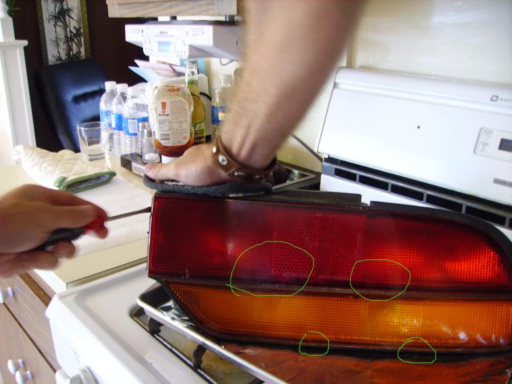
Again the best method is to lightly work the lenses out around the edges with the screwdriver, while putting most force on the lense from behind. Just push on the reflector housing inside and it will push the lens straight out from the main housing. If you've heated the glue up properly everything should slide out easily. Remember, if you're forcing the lens, you're not doing it right.
Sorry to beat a dead horse so much here, but trust me, you'll hate yourself if you crack one of your lenses.
Step 2: Preparing your LED board
One of the benefits of my design is it will save you a bit of money in the pcb board department. As I was unable to find enough pcb board to fill up both of the tails for a reasonable price, I decided simply to convert the reflector housing into my LED board, and it worked out quite nicely I think. Here's what you need to do
1st - trace out the basic shape of your reflector housing and cut it to shape until it fits inside the housing as shown in the pic.


2nd - Since you don't need to drill all the holes in a standard electrical pcb board, you just need to determine which ones will be occupied by your leds and transfer the design to your template. You'll need just one piece of electrical pcb board to do this.
My design for the Brake light uses vertical rows of 3x17 horizontal with an additional two rows that taper off to fill the corners. Therfore one brake light will require 54 red leds if you follow my design exactly. I achieved this count by making exact grids by overlaying my pcb test board with scotch tape, leaving only the holes open that would be occupied by my leds. The pictures will show what I'm explaining:

If you'll look closely, you'll see that the scotch tape perfectly laid out masks off 7 little holes, and when it's laid out in cross sections you're able to quickly mask off 7x7hole sections. As you work horizontally, you just need to leave one free row of holes between rows of tape. Vertically you'll leave two rows between tape sections. This will give you a nice perfectly spaced led grid.
Next lay your marked off pcb board over your templates you just cut out, line them up to where you want the leds to sit, and mark the holes with a fine mechanical pencil.
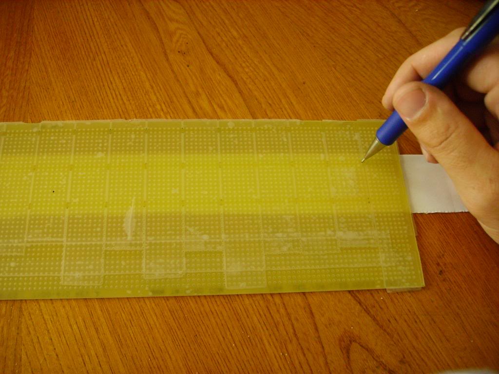
You can use the same masked pcb board for both the blinkers and brake portions of the tails. Just use two vertical rows only for the blinkers, while making three rows for the brakes. Furthermore, you don't need your pcb board to cover the entire length of the tail, it's sufficient to simply mark the drill points, and just shuffle the board down the length of your paper template. Just make sure the holes all line up. It's pretty simple stuff really.
From here you have two choices, you can use this paper as your drilling template. I personally chose to make something more durable in the event I wanted to create more of these, and also to facilitate easier drilling. So what I did was cut out a thin cardboard template to match the paper template. Scotch tape the two together, and use a thumbtack to punch through all the holes you just marked. ( you could possibly skip this step and just drill through the holes later, it's up to you) I personally did everything the long way as I wanted to ensure getting a perfectly straight end result.

Your end result should be some nifty drill guides that look something like this:

Now comes the fun part, drilling. Scotch tape your cardboard templates to the back of the reflector housings. Make sure everything is lined up the way you want it, and then drill away. You're going to need a dremel with a very tiny drill bit to do this!

and....TADA! you're very own custom pcb board, that magically will fit perfectly back into the tail light housing when you're all done:

Take note of where the corners of the housing taper off, You'll need to drill out and hollow these mounting points so that the led will be recessed back into the reflector housing, otherwise it will come in contact with the exterior lens upon reassembly.


Okay so by now you're probably ready to get down to business and get those LEDs glowing....
LED Mounting
Ok so by now you should have your reflector housings all nice and drilled and ready to go. For this part all you need is a pile of leds, a hot glue gun, and some good music. Before you start you have two options. You can test each LED you will use individually with your voltometer (assuming it has a diode test option) to make sure it's in working condition. Otherwise you can just mount everything and test after the fact to see if they work. Personally I just went the Plan B route, and everything worked out just fine. Now before you just go plunking LEDs into the slots, you need to make sure you understand the positive and negative side. Typically the positive side (anode) will have a longer leg, and if you look into the lens, you'll see the anode is the smaller of the two components inside. The negative (cathode) is typically the shorter of the two legs and is the larger "L" component inside the lens. Learn to identify it by looking into the lens itself, so that you'll be able to identify what is what even after the legs are shortened.

We'll be connecting the LEDs in series so you'll need to mount each diode with the positive side upward (really doesn't matter which side is up so long as your entire circuit is oriented the same way). Your leds should be arranged so that you can connect the negative foot of each diode to the positive foot of the diode beneath it.
And finally we'll want to make sure the LEDs are secure and all pointed in the same direction so we get a nice crisp light pattern. This is where the glue gun comes in. You'll want to apply a small bit of glue directly to the base of each LED, then insert it into the holes. DON'T try taking a shortcut by gluing the board directly, otherwise you'll wind up coating the legs of the LED as you insert it. This glue coating will make your life miserable come soldering time. Just glue the base of each diode, and the legs will stay nice and clean for soldering.

Once you've gotten all your LEDs mounted you should see your project starting to take shape. Again make sure all your diodes are nice and neat in straight rows. If you purchased high brightness red leds like I suggested you'll find they have a very narrow beam pattern, so it's important to make sure they're aimed properly and not sitting crooked in the housing. Should look something like this:

Soldering the Circuit
Okay, hopefully you've taken a break after gluing all those little suckers in, cause now comes the tedious albeit fun part (dunno but I like soldering). I'll show some pics of what you're aiming for and elaborate a bit on each one.


This is my basic boxy circuit design that will serve as the foundation. For the brake light portion I'm employing two seperate circuits. Each circuit has 9 rows of 3 leds in series. To accomplish this you'll need those plier snips i mentioned. For all the top leds, you can cut the positive leg down very short. For the negative legs you can cut those down by 1/2 to 2/3ds. For the entire middle row you can just cut the legs down by 1/2 to 2/3ds. For the bottom row you only need to cut the positive legs down by 1/2 to 2/3ds. Leave the negative legs at full length. Then as you can see from the picture, connect each led leg to leg to the diode beneath it. You should always be going negative to positive, otherwise the series won't light up. For the bottom legs that we left at full length, simply bend those towards the center of the circuit and overlap them a bit so that you can form one long ground connection. That's all there is too it really so just solder them up.
Here's more angles:


Now the corner sections of each light will require some special routing. The brake portions should look like this:
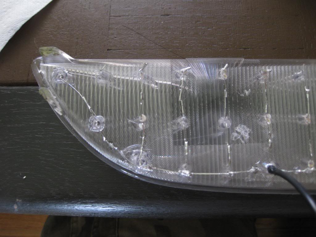

At this point I should probably note that for some of the connections your led legs won't reach, so just grab some of the scrap legs that you just snipped and solder those in to make the necessary connections.
The blinker portions are just simpler versions of the above. Instead of two separate circuits, the blinkers just need one long circuit. Each series will only be a series of two leds all sharing one common ground. Here's some pics, (don't worry about the resistors just yet, we'll get to those in a bit)


Same basic design. You've probably noticed the taped led in the corner though. If you were to just wire in the one led by itself, the electricity would follow the shortest/easiest path of least resistance, and just light that one lonely led. The proper work around to this would be to calculate a separate resistance value that would function in line with the other series'. However since I didn't feel like messing around with that I just soldered in an extra led to the back, and taped it up in black electrical tape. It doesn't hurt anything, but hey if you're feeling scholarly, play around with some resistance calculators, and you can skip this. Anyway here's some pics of my blinker corner led series.

Testing Your Soldering Might!
At this point it's probably a good idea to do some tests of the circuits you just soldered. You can connect a set of test wires to your car battery and/or a 9v batter will do fine for test purposes as well. Your test wires should have alligator clips for ease of use and safety. To test your circuits, simply connect the negative to the ground point. For the positive take one of your 1.5k or 470 resistors, clip it into your positive wire's test clip, and then you can touch the other end of the resistor foot to each led series to see if it's working. Please don't test without a resistor, otherwise you're gonna give your leds a dose of 12volts that I can guarantee they're not gonna like.
You'll want to test again later after hooking up all the resistors as well.
Resistors Resistors, and more Resistors
Now while you technically have a circuit, you're not done just yet, otherwise you'll just start fluxing out your leds. You'll notice when you purchase your leds they're rated in a couple different areas. MCD refers roughly to measured light output. However this doesn't mean necessarily that a 15000 mcd will be better for a tail light than an 8000. The reason being is that the higher the mcd value, the more narrow the focusing point of the lens will be, again roughly.
The next important thing to note is what current the led is rated at. Usually they'll have a maximum continuous current, and a peak current. Typically our red leds will run at 20ma (milliampers) max continuous current with a peak current of 30ma. We're not going to mess with peak currents. To achieve this level of operation you'll need things like pulse width modulators and such that will rapidly flash the led on and off. Anyway if you picked up the 8kmcd red leds like I suggested you'll find that they're more than sufficient, and even painful to look at directly.
Anyway circuits can get very complicated, and I pretty much only have a basic working knowledge of everything so I've opted to keep things simple. For our project we need to tone down the direct voltage from the battery to a level each diode can use, so that there's not too much current flowing through. Also avoid cranking more current than the led is rated for as this will shorten the led's lifespan and/or flux out the led. Also understand that from
First off for resistors we'll do the blinkers because they only need to function at one level of light. I used 470ohm 1/8 resistors because that's what I got for free with the leds I purchased and they worked just fine. If I remember correctly, for the blinkers each led was drawing about 19ma of current, which is perfect for their rating.
Each series needs its own resistor so for one blinker you'll need 18 470 resistors. Now just solder them in to the positive connection of the top led of each series. (You'll need to clip down one end of each resistor first) From there I chose to rout the other half of the resistor legs along the top part of the reflector housing. Just make sure your connections are above the resistor that leads to each series.


Simple as that, now just wire in some ample lengths of wiring to connect to the stock wiring connectors later and you're all done with the blinkers.
Now for the Taillights! The tail lights are evil, they gave me many many headaches trying to figure out how to work out a running light input and a brake light input that worked within the specifications of the leds, while maintaining proper brightness. I finally settled on two primary values of resistors: 1.5k for running lights (at this level each led gets about 6ma of current) and 470 for the brake lights. I also found however, that while each series tested out well independently, for some reason when I soldered it all up, at max output (brakes and running lights) each led was getting about 22-23ma. This is where the 220s come in. You'll be using one at the beginning of each running light circuit to tone down everything just slightly. By doing this your entire setup should run at max output at 20.1ma
Now you may be wondering how the lights will look in the daytime without the additional input of the running lights. Answer is nearly identical. Basically the running lights run at about 4-5ish ma per led, resulting in a bright, but not crazy bright glow. When the brake circuit is engaged as well, the whole assembly lights up as each led receives 20.1ma of current. Now for daytime use, without the running lights engaged, the brakes will simply light up each led at about 17ishma. There is very little discernable differenc to the eye between 17ma and 20ma so everything works out.
I spent many many many days and hours trying to work this out..........
Anyway for the brake housings you're going to need to wire in two separate resistor inputs to the beginning of each series. Soldering here is like a test of will and dexterity. To make things simpler I suggest using some scotch tape as your ally:

again like I said, just soldier one 1.5k resistor and 1 470 resistor to the positive leg stub of the lead led in each series:

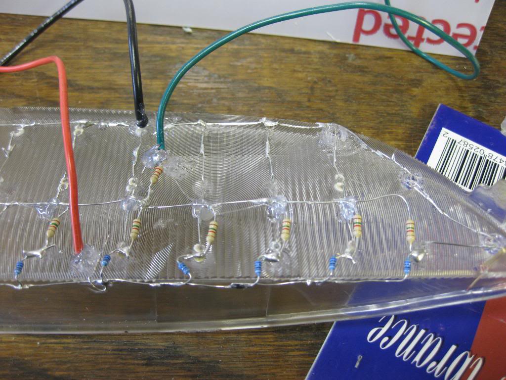
Once you get all the resistors soldered in, its just a matter of routing them. Now you've probably noticed that you can't route everything like the blinkers as the resistors will cross. Basically there's no way to do this without criss crossing one of the resistor sets. I chose to route the blue 470s above just like I did for the blinkers. For the 1.5ks I wired them together in a similar fashion, but routed them down below. They'll overlap your diode circuits, and this is okay just so long as the metal points don't touch one another. Once you've got everything all soldered up the way you like it, you'll want to insulate the cross over sections with a small bubble of hot glue to ensure the crossing sections never ever touch. Check out the pics and everything will make sense:

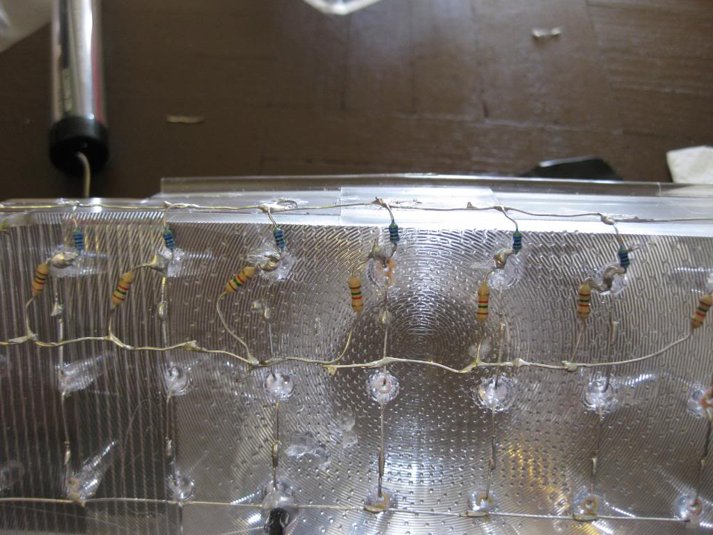

and finally glue the crossover sections, add in one 220ohm resistor to the beginning of the running lights, and solder in your wiring


Reassembly
Ok now it's time to put everything back together. To do this heat up the main headlight housing only:
[imghttps://2img.net/h/i192.photobucket.com/albums/z275/jordanmugen/IMGP0456-1.jpg[/img]
I found it's sufficient to just heat the housing alone. Warm it up for about the same time on the same settings (11-13 min at 225-240 degrees), then take it out and prepare to work quickly. lay the housing down on its back and carefully insert each of your precious reflector housings. Push them down in until they're all the way in, then work your lenses over the lip of the reflector housings and push them down and back into the primary tail light housing. Assuming you weren't too brutal during the removal process, everything should go back into place pretty much flush. Be careful with the amber lenses and be sure you get the tabs snapped all the way back into place. Also don't forget that you'll need to replace the screws you took out initially. I put them back in when the housing had cooled, and everything looks fine, though I imagine you can tighten everything down by another couple of millimeters if you replace the screws while the rubber glue is still warm and flexible.
Now there's room for improvement here I'm thinking. I'm personally wanting the lenses to stay very protected from water. Although you'll get everything back on nice and snug by reheating the main housing, I'm personally thinking that the removal process may compromise the integrity of the overall seal somewhat. (although the tail lights aren't exactly "sealed" like headlights are, given the nature of the rear oem bulb clip on housings)
I'm thinking that it might be a nice extra to add a small amount of hot glue to the edging of the main housing just to supplement the original glue a bit. Alternately you could also use RTV sealant, however I'm unsure how that would work should you need to reheat the assembly down the road. Regardless, just be aware that you'll really want to get everything squared away the first time around as the hot glue used in the construction of the led assembly will also get hot and may be compromised if and when you try to open up everything again. Not to worry though, LEDS last a long long long time, so you shouldn't have to worry about replacing anying in the near future, assuming you did everything correctly.
So by now you should be pretty much done. Just a matter of splicing the wires into the oem wiring.
Be aware that your tail lights will flash at that super fast rate. The reason being is that leds only use a small amount of power, so your car will think that the blinker bulb is out, and increase the flash time accordingly.
Some people like this, others don't. If you want your blinkers to continue to flash at the normal rate, just swing by the auto store and pick up some load resistors. I saw some at autozone the other day, something like 4 for 9 bucks.
Anyway, that's it for the writeup, here's some pics of my completed assembly for your viewing pleasure
